

- 1 Welcome to PRTG
- 2 Quick Start Guide
- 3 Using PRTG Hosted Monitor
- 4 Installing the Software
- 5 Understanding Basic Concepts
- 6 Basic Procedures
- 6.1 Login
- 6.2 Customer Service
- 6.3 Sensor States
- 6.4 Historic Data Reports
- 6.5 Similar Sensors
- 6.6 Recommended Sensors
- 6.7 Object Settings
- 6.8 Alarms
- 6.9 System Information
- 6.10 Logs
- 6.11 Tickets
- 6.12 Working with Table Lists
- 6.13 Object Selector
- 6.14 Priority and Favorites
- 6.15 Pause
- 6.16 Context Menus
- 6.17 Hover Popup
- 7 Device and Sensor Setup
- 7.1 Auto-Discovery
- 7.2 Create Objects Manually
- 7.3 Manage Device Tree
- 7.4 Root Group Settings
- 7.5 Probe Settings
- 7.6 Group Settings
- 7.7 Device Settings
- 7.8 Sensor Settings
- 7.8.1 Active Directory Replication Errors Sensor
- 7.8.2 ADO SQL v2 Sensor
- 7.8.3 Application Server Health (Autonomous) Sensor
- 7.8.4 AWS Alarm v2 Sensor
- 7.8.5 AWS Cost Sensor
- 7.8.6 AWS EBS v2 Sensor
- 7.8.7 AWS EC2 v2 Sensor
- 7.8.8 AWS ELB v2 Sensor
- 7.8.9 AWS RDS v2 Sensor
- 7.8.10 Beckhoff IPC System Health Sensor
- 7.8.11 Business Process Sensor
- 7.8.12 Cisco IP SLA Sensor
- 7.8.13 Cisco Meraki License Sensor
- 7.8.14 Cisco Meraki Network Health Sensor
- 7.8.15 Cisco WLC Access Point Overview Sensor
- 7.8.16 Citrix XenServer Host Sensor
- 7.8.17 Citrix XenServer Virtual Machine Sensor
- 7.8.18 Cloud HTTP v2 Sensor
- 7.8.19 Cloud Ping v2 Sensor
- 7.8.20 Cluster Health Sensor
- 7.8.21 Core Health Sensor
- 7.8.22 Core Health (Autonomous) Sensor
- 7.8.23 Dell EMC Unity Enclosure Health v2 Sensor
- 7.8.24 Dell EMC Unity File System v2 Sensor
- 7.8.25 Dell EMC Unity Storage Capacity v2 Sensor
- 7.8.26 Dell EMC Unity Storage LUN v2 Sensor
- 7.8.27 Dell EMC Unity Storage Pool v2 Sensor
- 7.8.28 Dell EMC Unity VMware Datastore v2 Sensor
- 7.8.29 Dell PowerVault MDi Logical Disk Sensor
- 7.8.30 Dell PowerVault MDi Physical Disk Sensor
- 7.8.31 DHCP Sensor
- 7.8.32 DICOM Bandwidth Sensor
- 7.8.33 DICOM C-ECHO Sensor
- 7.8.34 DICOM Query/Retrieve Sensor
- 7.8.35 DNS v2 Sensor
- 7.8.36 Docker Container Status Sensor
- 7.8.37 Event Log (Windows API) Sensor
- 7.8.38 Exchange Backup (PowerShell) Sensor
- 7.8.39 Exchange Database (PowerShell) Sensor
- 7.8.40 Exchange Database DAG (PowerShell) Sensor
- 7.8.41 Exchange Mail Queue (PowerShell) Sensor
- 7.8.42 Exchange Mailbox (PowerShell) Sensor
- 7.8.43 Exchange Public Folder (PowerShell) Sensor
- 7.8.44 EXE/Script Sensor
- 7.8.45 EXE/Script Advanced Sensor
- 7.8.46 File Sensor
- 7.8.47 File Content Sensor
- 7.8.48 Folder Sensor
- 7.8.49 FortiGate System Statistics Sensor
- 7.8.50 FortiGate VPN Overview Sensor
- 7.8.51 FTP Sensor
- 7.8.52 FTP v2 Sensor
- 7.8.53 FTP Server File Count Sensor
- 7.8.54 FTP Server File Count v2 Sensor
- 7.8.55 HL7 Sensor
- 7.8.56 HPE 3PAR Common Provisioning Group Sensor
- 7.8.57 HPE 3PAR Drive Enclosure Sensor
- 7.8.58 HPE 3PAR Virtual Volume Sensor
- 7.8.59 HTTP Sensor
- 7.8.60 HTTP v2 Sensor
- 7.8.61 HTTP Advanced Sensor
- 7.8.62 HTTP Apache ModStatus PerfStats Sensor
- 7.8.63 HTTP Apache ModStatus Totals Sensor
- 7.8.64 HTTP Content Sensor
- 7.8.65 HTTP Data Advanced Sensor
- 7.8.66 HTTP IoT Push Data Advanced Sensor
- 7.8.67 HTTP Push Count Sensor
- 7.8.68 HTTP Push Data Sensor
- 7.8.69 HTTP Push Data Advanced Sensor
- 7.8.70 HTTP Transaction Sensor
- 7.8.71 HTTP Webpage Sensor
- 7.8.72 HTTP XML/REST Value Sensor
- 7.8.73 Hyper-V Cluster Shared Volume Disk Free Sensor
- 7.8.74 Hyper-V Host Server Sensor
- 7.8.75 Hyper-V Virtual Machine Sensor
- 7.8.76 Hyper-V Virtual Network Adapter Sensor
- 7.8.77 Hyper-V Virtual Storage Device Sensor
- 7.8.78 IMAP Sensor
- 7.8.79 IP on DNS Blacklist Sensor
- 7.8.80 IP Reputation Score Sensor
- 7.8.81 IPFIX Sensor
- 7.8.82 IPFIX (Custom) Sensor
- 7.8.83 IPMI System Health Sensor
- 7.8.84 jFlow v5 Sensor
- 7.8.85 jFlow v5 (Custom) Sensor
- 7.8.86 LDAP Sensor
- 7.8.87 Local Folder Sensor
- 7.8.88 Microsoft 365 Mailbox Sensor
- 7.8.89 Microsoft 365 Service Status Sensor
- 7.8.90 Microsoft 365 Service Status Advanced Sensor
- 7.8.91 Microsoft Azure SQL Database Sensor
- 7.8.92 Microsoft Azure Storage Account Sensor
- 7.8.93 Microsoft Azure Subscription Cost Sensor
- 7.8.94 Microsoft Azure Virtual Machine Sensor
- 7.8.95 Microsoft SQL v2 Sensor
- 7.8.96 Modbus RTU Custom Sensor
- 7.8.97 Modbus TCP Custom Sensor
- 7.8.98 MQTT Round Trip Sensor
- 7.8.99 MQTT Statistics Sensor
- 7.8.100 MQTT Subscribe Custom Sensor
- 7.8.101 Multi-Platform Probe Connection Health (Autonomous) Sensor
- 7.8.102 Multi-Platform Probe Health Sensor
- 7.8.103 MySQL v2 Sensor
- 7.8.104 NATS Server Overview Sensor
- 7.8.105 NetApp Aggregate Sensor
- 7.8.106 NetApp Aggregate v2 Sensor
- 7.8.107 NetApp I/O Sensor
- 7.8.108 NetApp I/O v2 Sensor
- 7.8.109 NetApp LIF Sensor
- 7.8.110 NetApp LIF v2 Sensor
- 7.8.111 NetApp LUN Sensor
- 7.8.112 NetApp LUN v2 Sensor
- 7.8.113 NetApp NIC Sensor
- 7.8.114 NetApp NIC v2 Sensor
- 7.8.115 NetApp Physical Disk Sensor
- 7.8.116 NetApp Physical Disk v2 Sensor
- 7.8.117 NetApp SnapMirror Sensor
- 7.8.118 NetApp SnapMirror v2 Sensor
- 7.8.119 NetApp System Health Sensor
- 7.8.120 NetApp System Health v2 Sensor
- 7.8.121 NetApp Volume Sensor
- 7.8.122 NetApp Volume v2 Sensor
- 7.8.123 NetFlow v5 Sensor
- 7.8.124 NetFlow v5 (Custom) Sensor
- 7.8.125 NetFlow v9 Sensor
- 7.8.126 NetFlow v9 (Custom) Sensor
- 7.8.127 Network Share Sensor
- 7.8.128 OPC UA Certificate Sensor
- 7.8.129 OPC UA Custom Sensor
- 7.8.130 OPC UA Server Status Sensor
- 7.8.131 Oracle SQL v2 Sensor
- 7.8.132 Oracle Tablespace Sensor
- 7.8.133 Packet Sniffer Sensor
- 7.8.134 Packet Sniffer (Custom) Sensor
- 7.8.135 PerfCounter Custom Sensor
- 7.8.136 PerfCounter IIS Application Pool Sensor
- 7.8.137 Ping Sensor
- 7.8.138 Ping v2 Sensor
- 7.8.139 Ping Jitter Sensor
- 7.8.140 Ping Jitter v2 Sensor
- 7.8.141 POP3 Sensor
- 7.8.142 Port Sensor
- 7.8.143 Port v2 Sensor
- 7.8.144 Port Range Sensor
- 7.8.145 PostgreSQL Sensor
- 7.8.146 Probe Health Sensor
- 7.8.147 Proxmox VE Cluster Health Sensor
- 7.8.148 Proxmox VE Container Status Sensor
- 7.8.149 Proxmox VE Virtual Machine Status Sensor
- 7.8.150 Proxmox VE Node Performance Sensor
- 7.8.151 PRTG Data Hub Process Sensor
- 7.8.152 PRTG Data Hub Rule Sensor
- 7.8.153 PRTG Data Hub Traffic Sensor
- 7.8.154 QoS (Quality of Service) One Way Sensor
- 7.8.155 QoS (Quality of Service) Round Trip Sensor
- 7.8.156 RADIUS v2 Sensor
- 7.8.157 RDP (Remote Desktop) Sensor
- 7.8.158 RDP Client-Side Check Sensor
- 7.8.159 Redfish Fan Status Sensor
- 7.8.160 Redfish Power Supply Sensor
- 7.8.161 Redfish System Health Sensor
- 7.8.162 Redfish Temperature Sensor
- 7.8.163 Redfish Virtual Disk Sensor
- 7.8.164 REST Custom Sensor
- 7.8.165 REST Custom v2 Sensor
- 7.8.166 REST JSON Data Sensor
- 7.8.167 Script v2 Sensor
- 7.8.168 Sensor Factory Sensor
- 7.8.169 sFlow Sensor
- 7.8.170 sFlow (Custom) Sensor
- 7.8.171 Share Disk Free Sensor
- 7.8.172 SIMATIC S7-1200/1500 Alarm Status Sensor (BETA)
- 7.8.173 SIMATIC S7-1200/1500 CPU Status Sensor
- 7.8.174 SIMATIC S7-1200/1500 Hardware Status Sensor (BETA)
- 7.8.175 SIMATIC S7-300/400 CPU Restart Overview Sensor (BETA)
- 7.8.176 SIMATIC S7-300/400 CPU Status Sensor (BETA)
- 7.8.177 SIMATIC S7-300/400 Custom Process Data Sensor (BETA)
- 7.8.178 SIMATIC S7-300/400 LED Status (BETA)
- 7.8.179 SIP Options Ping Sensor
- 7.8.180 SMTP Sensor
- 7.8.181 SMTP&IMAP Round Trip Sensor
- 7.8.182 SMTP&POP3 Round Trip Sensor
- 7.8.183 SNMP APC Hardware Sensor
- 7.8.184 SNMP Buffalo TS System Health Sensor
- 7.8.185 SNMP Cisco ADSL Sensor
- 7.8.186 SNMP Cisco ASA VPN Connections Sensor
- 7.8.187 SNMP Cisco ASA VPN Traffic Sensor
- 7.8.188 SNMP Cisco ASA VPN Users Sensor
- 7.8.189 SNMP Cisco CBQoS Sensor
- 7.8.190 SNMP Cisco System Health Sensor
- 7.8.191 SNMP Cisco UCS Blade Sensor
- 7.8.192 SNMP Cisco UCS Chassis Sensor
- 7.8.193 SNMP Cisco UCS Physical Disk Sensor
- 7.8.194 SNMP Cisco UCS System Health Sensor
- 7.8.195 SNMP CPU Load Sensor
- 7.8.196 SNMP CPU Usage Sensor
- 7.8.197 SNMP Custom Sensor
- 7.8.198 SNMP Custom Advanced Sensor
- 7.8.199 SNMP Custom String Sensor
- 7.8.200 SNMP Custom String v2 Sensor
- 7.8.201 SNMP Custom String Lookup Sensor
- 7.8.202 SNMP Custom Table Sensor
- 7.8.203 SNMP Custom v2 Sensor
- 7.8.204 SNMP Dell EqualLogic Logical Disk Sensor
- 7.8.205 SNMP Dell EqualLogic Member Health Sensor
- 7.8.206 SNMP Dell EqualLogic Physical Disk Sensor
- 7.8.207 SNMP Dell Hardware Sensor
- 7.8.208 SNMP Dell PowerEdge Physical Disk Sensor
- 7.8.209 SNMP Dell PowerEdge System Health Sensor
- 7.8.210 SNMP Disk Free Sensor
- 7.8.211 SNMP Disk Free v2 Sensor
- 7.8.212 SNMP Fujitsu System Health v2 Sensor
- 7.8.213 SNMP Hardware Status Sensor
- 7.8.214 SNMP HP LaserJet Hardware Sensor
- 7.8.215 SNMP HPE BladeSystem Blade Sensor
- 7.8.216 SNMP HPE BladeSystem Enclosure Health Sensor
- 7.8.217 SNMP HPE ProLiant Logical Disk Sensor
- 7.8.218 SNMP HPE ProLiant Memory Controller Sensor
- 7.8.219 SNMP HPE ProLiant Network Interface Sensor
- 7.8.220 SNMP HPE ProLiant Physical Disk Sensor
- 7.8.221 SNMP HPE ProLiant System Health Sensor
- 7.8.222 SNMP IBM System X Logical Disk Sensor
- 7.8.223 SNMP IBM System X Physical Disk Sensor
- 7.8.224 SNMP IBM System X Physical Memory Sensor
- 7.8.225 SNMP IBM System X System Health Sensor
- 7.8.226 SNMP interSeptor Pro Environment Sensor
- 7.8.227 SNMP Juniper NS System Health Sensor
- 7.8.228 SNMP LenovoEMC Physical Disk Sensor
- 7.8.229 SNMP LenovoEMC System Health Sensor
- 7.8.230 SNMP Library Sensor
- 7.8.231 SNMP Linux Block Device I/O Sensor
- 7.8.232 SNMP Linux Disk Free Sensor
- 7.8.233 SNMP Linux Disk Free v2 Sensor
- 7.8.234 SNMP Linux Load Average Sensor
- 7.8.235 SNMP Linux Load Average v2 Sensor
- 7.8.236 SNMP Linux Meminfo Sensor
- 7.8.237 SNMP Linux Meminfo v2 Sensor
- 7.8.238 SNMP Linux Physical Disk Sensor
- 7.8.239 SNMP Memory Sensor
- 7.8.240 SNMP Memory v2 Sensor
- 7.8.241 SNMP NetApp Disk Free Sensor
- 7.8.242 SNMP NetApp Enclosure Sensor
- 7.8.243 SNMP NetApp I/O Sensor
- 7.8.244 SNMP NetApp License Sensor
- 7.8.245 SNMP NetApp Logical Unit Sensor
- 7.8.246 SNMP NetApp Network Interface Sensor
- 7.8.247 SNMP NetApp System Health Sensor
- 7.8.248 SNMP Nutanix Cluster Health Sensor
- 7.8.249 SNMP Nutanix Hypervisor Sensor
- 7.8.250 SNMP Poseidon Environment Sensor
- 7.8.251 SNMP Printer Sensor
- 7.8.252 SNMP Printer v2 Sensor
- 7.8.253 SNMP QNAP Logical Disk Sensor
- 7.8.254 SNMP QNAP Physical Disk Sensor
- 7.8.255 SNMP QNAP System Health Sensor
- 7.8.256 SNMP Rittal CMC III Hardware Status Sensor
- 7.8.257 SNMP RMON Sensor
- 7.8.258 SNMP RMON v2 Sensor
- 7.8.259 SNMP SonicWall System Health Sensor
- 7.8.260 SNMP SonicWall VPN Traffic Sensor
- 7.8.261 SNMP Synology Logical Disk Sensor
- 7.8.262 SNMP Synology Physical Disk Sensor
- 7.8.263 SNMP Synology System Health Sensor
- 7.8.264 SNMP System Uptime Sensor
- 7.8.265 SNMP Traffic Sensor
- 7.8.266 SNMP Traffic v2 Sensor
- 7.8.267 SNMP Trap Receiver Sensor
- 7.8.268 SNMP UPS Status Sensor
- 7.8.269 SNMP Uptime v2 Sensor
- 7.8.270 SNMP Windows Service v2 Sensor
- 7.8.271 SNMP Windows Service Sensor
- 7.8.272 SNTP Sensor
- 7.8.273 SNTP v2 Sensor
- 7.8.274 Soffico Orchestra Channel Health Sensor
- 7.8.275 Soffico Orchestra Scenario Sensor
- 7.8.276 SSH Disk Free v2 Sensor
- 7.8.277 SSH INodes Free v2 Sensor
- 7.8.278 SSH Load Average v2 Sensor
- 7.8.279 SSH Meminfo v2 Sensor
- 7.8.280 SSH Remote Ping v2 Sensor
- 7.8.281 SSH SAN Enclosure Sensor
- 7.8.282 SSH SAN Logical Disk Sensor
- 7.8.283 SSH SAN Physical Disk Sensor
- 7.8.284 SSH SAN System Health Sensor
- 7.8.285 SSH Script Sensor
- 7.8.286 SSH Script v2 Sensor
- 7.8.287 SSH Script Advanced Sensor
- 7.8.288 SSL Certificate Sensor
- 7.8.289 SSL Security Check Sensor
- 7.8.290 SSL/TLS Certificate Sensor
- 7.8.291 SSL/TLS Security Check Sensor
- 7.8.292 Syslog Receiver Sensor
- 7.8.293 System Health Sensor
- 7.8.294 System Health v2 Sensor
- 7.8.295 TFTP Sensor
- 7.8.296 Traceroute Hop Count Sensor
- 7.8.297 Traceroute Hop Count v2 Sensor
- 7.8.298 Veeam Backup Job Status Sensor
- 7.8.299 Veeam Backup Job Status Advanced Sensor
- 7.8.300 VMware Datastore (REST) Sensor
- 7.8.301 VMware Datastore (SOAP) Sensor
- 7.8.302 VMware Host Hardware (WBEM) Sensor
- 7.8.303 VMware Host Hardware Status (SOAP) Sensor
- 7.8.304 VMware Host Performance (REST & VI/JSON) Sensor
- 7.8.305 VMware Host Performance (SOAP) Sensor
- 7.8.306 VMware Virtual Machine (REST & VI/JSON) Sensor
- 7.8.307 VMware Virtual Machine (SOAP) Sensor
- 7.8.308 Windows CPU Load Sensor
- 7.8.309 Windows IIS Application Sensor
- 7.8.310 Windows MSMQ Queue Length Sensor
- 7.8.311 Windows Network Card Sensor
- 7.8.312 Windows Pagefile Sensor
- 7.8.313 Windows Physical Disk I/O Sensor
- 7.8.314 Windows Print Queue Sensor
- 7.8.315 Windows Process Sensor
- 7.8.316 Windows SMTP Service Received Sensor
- 7.8.317 Windows SMTP Service Sent Sensor
- 7.8.318 Windows System Uptime Sensor
- 7.8.319 Windows Updates Status (PowerShell) Sensor
- 7.8.320 WMI Battery Sensor
- 7.8.321 WMI CPU Load v2 Sensor
- 7.8.322 WMI Custom Sensor
- 7.8.323 WMI Custom String Sensor
- 7.8.324 WMI Disk Health Sensor
- 7.8.325 WMI Event Log Sensor
- 7.8.326 WMI Exchange Server Sensor
- 7.8.327 WMI Exchange Transport Queue Sensor
- 7.8.328 WMI File Sensor
- 7.8.329 WMI Free Disk Space (Multi Disk) Sensor
- 7.8.330 WMI HDD Health Sensor
- 7.8.331 WMI Logical Disk I/O Sensor
- 7.8.332 WMI Logical Disk I/O v2 Sensor
- 7.8.333 WMI Memory Sensor
- 7.8.334 WMI Memory v2 Sensor
- 7.8.335 WMI Microsoft IIS Application v2 Sensor
- 7.8.336 WMI Microsoft SQL Server Sensor
- 7.8.337 WMI Microsoft SQL Server 2005 Sensor (Deprecated)
- 7.8.338 WMI Microsoft SQL Server 2008 Sensor
- 7.8.339 WMI Microsoft SQL Server 2012 Sensor
- 7.8.340 WMI Microsoft SQL Server 2014 Sensor
- 7.8.341 WMI Microsoft SQL Server 2016 Sensor
- 7.8.342 WMI Microsoft SQL Server 2017 Sensor
- 7.8.343 WMI Microsoft SQL Server 2019 Sensor
- 7.8.344 WMI Microsoft SQL Server 2022 Sensor
- 7.8.345 WMI Network Card v2 Sensor
- 7.8.346 WMI Pagefile v2 Sensor
- 7.8.347 WMI Physical Disk I/O v2 Sensor
- 7.8.348 WMI Print Queue v2 Sensor
- 7.8.349 WMI Remote Ping Sensor
- 7.8.350 WMI Security Center Sensor
- 7.8.351 WMI Service Sensor
- 7.8.352 WMI Service v2 Sensor (BETA)
- 7.8.353 WMI Share Sensor
- 7.8.354 WMI SharePoint Process Sensor
- 7.8.355 WMI Storage Pool Sensor
- 7.8.356 WMI System Uptime v2 Sensor
- 7.8.357 WMI Terminal Services (Windows 2008+) Sensor
- 7.8.358 WMI Terminal Services (Windows XP/Vista/2003) Sensor
- 7.8.359 WMI UTC Time Sensor
- 7.8.360 WMI Vital System Data v2 Sensor
- 7.8.361 WMI Volume Sensor
- 7.8.362 WMI Volume v2 Sensor
- 7.8.363 WMI Windows Security Sensor
- 7.8.364 WSUS Statistics Sensor
- 7.8.365 Zoom Service Status Sensor
- 7.9 Additional Sensor Types (Custom Sensors)
- 7.10 Channel Settings
- 7.11 Notification Triggers Settings
- 8 Advanced Procedures
- 8.1 Toplists
- 8.2 Move Objects
- 8.3 Clone Object
- 8.4 Multi-Edit
- 8.5 Create Device Template
- 8.6 Show Dependencies
- 8.7 Geo Maps
- 8.8 Notifications
- 8.9 Libraries
- 8.10 Reports
- 8.11 Maps
- 8.12 Setup
- 9 Desktop Notifications
- 10 Sensor Technologies
- 10.1 Monitoring via SNMP
- 10.2 Monitoring via WMI
- 10.3 Monitoring via SSH
- 10.4 Monitoring Bandwidth via Packet Sniffing
- 10.5 Monitoring Bandwidth via Flows
- 10.6 Bandwidth Monitoring Comparison
- 10.7 Monitoring Quality of Service
- 10.8 Monitoring Backups
- 10.9 Monitoring Virtual Environments
- 10.10 Monitoring Databases
- 10.11 Monitoring via HTTP
- 11 PRTG Administration Tool
- 12 Advanced Topics
- 12.1 Active Directory Integration
- 12.2 Application Programming Interface (API) Definition
- 12.3 Filter Rules for Flow, IPFIX, and Packet Sniffer Sensors
- 12.4 Channel Definitions for Flow, IPFIX, and Packet Sniffer Sensors
- 12.5 Define IP Address Ranges
- 12.6 Define Lookups
- 12.7 Regular Expressions
- 12.8 Calculating Percentiles
- 12.9 Add Remote Probe
- 12.10 Failover Cluster Configuration
- 12.11 Data Storage
- 13 Appendix
- 13.1 Abbreviations
- 13.2 Available Sensor Types
- 13.3 Default Ports
- 13.4 Differences between PRTG Network Monitor and PRTG Hosted Monitor
- 13.5 Escape Special Characters and Whitespaces in Parameters
- 13.6 Glossary
- 13.7 Icons
- 13.8 Legal Notices
- 13.9 Placeholders for Notifications
- 13.10 Standard Lookup Files
- 13.11 Supported AWS Regions and Their Codes
User Manual - Contents
 This sensor is in beta status. The operating methods and the available settings are still subject to change. Do not expect that all functions work properly, or that this sensor works as expected at all.
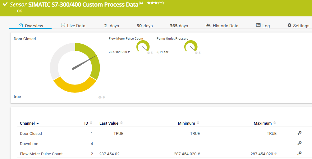
 For a detailed list and descriptions of the channels that this sensor can show, see section




 This option is not available when the sensor runs on the hosted probe of a PRTG Hosted Monitor instance.
 under the corresponding setting name to disable the inheritance and to display its options.
